 EN
EN


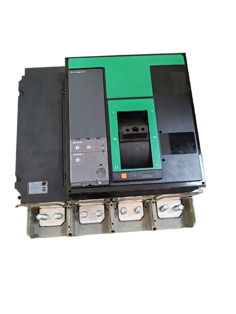
Direct current systems present unique challenges that fundamentally differ from alternating current applications, particularly in circuit protection. Understanding how a DC molded case circuit breaker operates under direct current loads is essential for engineers designing photovoltaic installations, battery storage systems, electric vehicle charging infrastructure, and industrial DC power networks. Unlike AC systems where current naturally crosses zero twice per cycle, DC loads maintain continuous unidirectional flow, creating arc extinction challenges that demand specialized breaker design and interrupt mechanisms tailored specifically for direct current characteristics.
The operational mechanism of a DC molded case circuit breaker involves sophisticated arc suppression technology, magnetic blow-out systems, and contact design optimized for the physics of direct current interruption. When protecting DC loads ranging from solar arrays to data center backup systems, these breakers must overcome the absence of natural current zero crossings while managing the stored energy inherent in inductive DC circuits. This technical exploration examines the precise methods through which DC molded case circuit breakers detect faults, initiate interruption sequences, extinguish DC arcs, and safely isolate direct current loads across voltage levels from 250V to 1500V in modern power systems.
Fundamental Principles of DC Current Interruption
The DC Arc Challenge Compared to AC Systems
The core challenge in DC load interruption stems from the continuous nature of direct current flow. In alternating current systems, the current naturally passes through zero amplitude 100 or 120 times per second depending on frequency, providing natural opportunities for arc extinction. A DC molded case circuit breaker confronts sustained current flow without these natural zero crossings, meaning the arc formed when contacts separate receives continuous energy that sustains the plasma channel. This fundamental difference requires DC breakers to forcibly create conditions that suppress arc energy below the minimum threshold needed to maintain ionization.
The energy stored in DC circuits, particularly those with inductive components like motors, solenoids, and long cable runs, further complicates interruption. When a DC molded case circuit breaker opens under load, the inductance resists current change according to the relationship V = L(di/dt), generating high voltage transients that can reach several times the system voltage. These transients provide additional energy to sustain the arc and can cause contact erosion, insulation failure, or breaker damage if not properly managed through coordinated arc suppression mechanisms and energy absorption strategies.
Contact Separation Velocity and Gap Distance Requirements
A DC molded case circuit breaker employs rapid contact separation as the first line of defense against arc sustainability. The stored energy mechanism, typically a spring system charged during the closing operation, releases with sufficient force to achieve contact separation speeds exceeding 5 meters per second in quality breakers. This rapid separation quickly increases the arc length, raising its resistance and voltage drop, which begins to reduce the energy available to sustain ionization. The mechanical design must ensure consistent separation velocity across the operational life despite contact wear and environmental variations.
The final contact gap distance in a DC molded case circuit breaker must exceed AC breaker requirements due to the higher dielectric stress and absence of periodic voltage zero crossings. For 1000V DC systems, contact gaps typically range from 12mm to 18mm, compared to 8mm to 12mm for equivalent AC voltage ratings. This increased separation provides adequate dielectric strength to withstand both the steady-state DC voltage and the inductive transient spikes that occur during interruption. The gap distance must account for altitude derating, pollution levels, and the voltage class of the protected DC load to ensure reliable isolation.
Series Contact Configuration for Enhanced Interruption
Many advanced DC molded case circuit breakers utilize series-connected contact sets per pole to distribute the arc voltage across multiple breaking points. This configuration allows each contact set to extinguish a portion of the total arc, effectively dividing the interruption task among multiple gaps. For high-voltage DC applications such as 1500V photovoltaic systems, a DC molded case circuit breaker may incorporate two or three contact sets in series per pole, each contributing 500V to 750V of arc voltage capability.
The series contact arrangement in a DC molded case circuit breaker provides redundancy and improved reliability since the arc must be sustained across multiple gaps simultaneously. The spacing between series contacts must be optimized to prevent arc bridging while ensuring compact overall dimensions. Modern designs incorporate barriers between contact sets to prevent arc plasma from one gap influencing adjacent gaps, maintaining independent arc extinction at each interruption point. This topology significantly enhances the breaking capacity available for high-power DC loads without proportionally increasing breaker size.
Arc Extinguishing Mechanisms in DC Breaker Design
Magnetic Blow-Out Systems for Arc Deflection
The magnetic blow-out coil represents a critical component in how a DC molded case circuit breaker manages arc extinction. This coil, positioned adjacent to the contact area, carries the fault current and generates a magnetic field perpendicular to the arc plasma. According to the Lorentz force principle, the current-carrying arc plasma experiences a force that drives it away from the contacts and into specially designed arc chutes. The magnetic force increases proportionally with fault current magnitude, providing stronger arc deflection precisely when interrupting capability is most needed for severe DC load faults.
The geometry and positioning of the magnetic blow-out system in a DC molded case circuit breaker must account for the unidirectional nature of DC current. Unlike AC breakers where polarity reverses, DC applications require consistent magnetic field orientation to ensure reliable arc movement toward the arc chutes regardless of which contact serves as anode or cathode. Advanced designs incorporate permanent magnets in conjunction with electromagnetic coils to provide baseline magnetic flux even at low current levels, ensuring arc deflection begins immediately upon contact separation rather than waiting for sufficient fault current to energize the blow-out coil.
Arc Chute Design and Deionization Plates
Once the magnetic force drives the arc away from the main contacts, a DC molded case circuit breaker relies on arc chutes composed of ferromagnetic deionization plates to complete extinction. These closely-spaced steel plates, typically separated by 1mm to 3mm gaps, serve multiple functions in managing DC loads. First, they subdivide the single long arc into many short series arcs, each with its own cathode and anode voltage drops totaling approximately 20V to 40V per segment. For a 1000V DC system, this can create 25 to 50 separate arc segments, dramatically increasing total arc voltage.
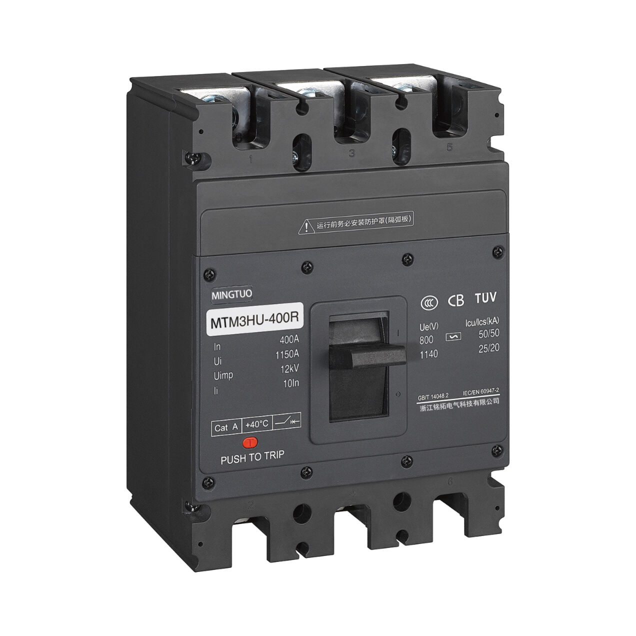
The ferromagnetic material of the arc chute plates in a DC molded case circuit breaker enhances magnetic field concentration, further accelerating arc movement into the chute structure. As the arc segments form between successive plates, each segment experiences cooling through thermal conduction to the metal plates, radiation to surrounding surfaces, and convection as hot gases rise through the chute assembly. The cumulative arc voltage developed across all segments eventually exceeds the system voltage, forcing current toward zero and enabling arc extinction. The number of plates, their spacing, and material properties must be precisely engineered for the specific voltage and current ratings of the DC load being protected.
Arc Voltage Generation and Current Zero Forcing
The extinction process in a DC molded case circuit breaker fundamentally relies on raising the arc voltage above the source voltage, creating a condition where the circuit can no longer sustain current flow. Each segment of arc between deionization plates contributes voltage drop comprising the cathode fall (approximately 10V to 15V), anode fall (approximately 10V to 15V), and the positive column voltage gradient (approximately 5V to 20V per millimeter depending on current magnitude). As the arc lengthens and subdivides, the total voltage requirement to maintain all arc segments eventually exceeds the available system voltage.
When arc voltage exceeds source voltage in a DC molded case circuit breaker protecting inductive DC loads, the relationship V_source = L(di/dt) + V_arc dictates that current must decrease. The rate of current reduction depends on circuit inductance, with higher inductance slowing the current decay but also generating higher voltage transients. Quality DC molded case circuit breakers include surge absorption components, typically metal oxide varistors, connected across the contacts to clamp these transient voltages to safe levels while allowing the arc extinction process to proceed. The breaker must maintain adequate dielectric strength in its open gap even while these transients stress the insulation system.
Thermal and Magnetic Trip Mechanisms for DC Applications
Bimetallic Thermal Overload Protection
The thermal protection mechanism in a DC molded case circuit breaker uses a bimetallic strip that deflects when heated by load current passing through it. This strip consists of two bonded metals with different thermal expansion coefficients, causing predictable bending as temperature rises. For DC loads with continuous current flow, the thermal response provides inverse-time characteristics where moderate overloads take minutes to trip while severe overloads trip more quickly. The bimetallic element must be calibrated considering the DC current's heating effect, which differs from AC due to the absence of RMS/peak current relationships and skin effect considerations.
Ambient temperature compensation represents an important design consideration in DC molded case circuit breakers used for outdoor photovoltaic installations or industrial environments with wide temperature variations. A compensating bimetallic element, arranged to oppose the main sensing element's ambient temperature response, ensures that trip characteristics remain consistent whether the DC load operates in summer heat or winter cold. Without proper compensation, a breaker might nuisance-trip in high ambient temperatures or fail to protect adequately in cold conditions, both problematic for critical DC systems like data center power distribution or telecom backup supplies.
Electromagnetic Instantaneous Trip Function
For short-circuit protection of DC loads, a DC molded case circuit breaker incorporates an electromagnetic trip unit consisting of a solenoid coil and a spring-restrained armature. When fault current exceeds the instantaneous trip threshold, typically 5 to 15 times the rated current, the magnetic force generated by the coil overcomes the spring restraint and drives the armature to trip the breaker mechanism. This response occurs within milliseconds, providing fast fault clearing essential to protect cables, busbars, and equipment from short-circuit damage. The magnetic circuit design must account for the steady magnetic field produced by DC current, which differs from the alternating flux in AC applications.
The pickup current setting for the electromagnetic trip in a DC molded case circuit breaker requires careful coordination with the DC load characteristics and upstream protection devices. Solar inverters, for example, can source fault current limited to approximately 1.2 to 1.5 times their rated output current, necessitating that the breaker's instantaneous trip threshold be set appropriately low or that alternative fast-acting protection be employed. Battery systems, conversely, can deliver very high short-circuit currents limited primarily by internal resistance and cable impedance, requiring the DC molded case circuit breaker to have adequate interrupting capacity, often specified as 10kA, 25kA, 50kA, or higher depending on system design.
Electronic Trip Units for Advanced DC Protection
Advanced DC molded case circuit breakers increasingly incorporate microprocessor-based electronic trip units that provide precision protection tailored to DC load profiles. These units measure current through Hall effect sensors or Rogowski coils, analyze the waveform digitally, and can implement sophisticated protection algorithms including ground fault detection, arc fault detection, and communication capabilities for integration into supervisory systems. Electronic trip units offer adjustable time-current characteristics, enabling a single breaker model to protect diverse DC applications from battery charging systems to motor drives.
The power supply for electronic trip units in a DC molded case circuit breaker typically derives from the load current itself, using current transformers or direct sensing with voltage regulation. This self-powered approach ensures the protection function remains operational whenever current flows, without requiring auxiliary power supplies. For very low current conditions approaching the trip unit's minimum operating threshold, some designs incorporate supercapacitors or batteries to maintain protection during startup or light load conditions. The electronic trip unit can also provide diagnostic information, recording trip events, current trends, and operational parameters useful for DC system maintenance and optimization.
Application-Specific Considerations for DC Load Protection
Photovoltaic System Protection Requirements
Solar photovoltaic systems represent one of the most demanding applications for a DC molded case circuit breaker due to the combination of high voltage (up to 1500V for modern utility-scale systems), limited fault current available from PV arrays, and continuous exposure to environmental stresses. A properly specified DC molded case circuit breaker for PV applications must be rated for the maximum system voltage, certified to relevant standards such as IEC 60947-2 Annex B or UL 489 Supplement SB, and have sufficient interrupting capacity for both array short-circuits and inverter backfeed scenarios.
The DC load characteristics of photovoltaic arrays differ significantly from battery or motor loads because fault current from the array itself is inherently limited to approximately 1.25 to 1.5 times the short-circuit current rating. This means a DC molded case circuit breaker protecting array circuits may need adjustable instantaneous trip settings or coordination with upstream protection to prevent nuisance tripping during normal transients like cloud-edge effects or inverter startup. Conversely, backfeed from the inverter during utility grid faults can inject significant fault current into array circuits, requiring the breaker to handle bidirectional current flow and have adequate reverse-current breaking capability.
Battery Energy Storage System Protection
Battery systems present unique challenges for a DC molded case circuit breaker due to their very low source impedance and resulting high available fault current. Lithium-ion battery arrays, particularly those used in grid storage or electric vehicle charging applications, can deliver short-circuit currents exceeding 50kA to 100kA depending on system size and battery chemistry. The DC molded case circuit breaker must be rated for these high interrupting requirements while also accommodating the continuous load current during normal charge and discharge cycles.
Coordination between multiple DC molded case circuit breakers in battery systems requires careful analysis of time-current curves to ensure selective tripping. A fault in a battery string should trip only the breaker protecting that string, not upstream breakers that would unnecessarily interrupt the entire system. This selectivity is more challenging in DC systems compared to AC because the fault current magnitude may not vary significantly between different fault locations. Electronic trip units with communication capabilities allow coordination through zone selective interlocking, where breakers communicate to ensure only the device closest to the fault trips, maintaining DC load continuity for unfaulted portions of the system.
Industrial DC Motor and Drive Applications
DC motor drives for industrial applications such as cranes, elevators, mining equipment, and metal rolling mills impose dynamic loading on a DC molded case circuit breaker protecting the feeder circuits. These loads exhibit high inrush current during motor starting, regenerative braking current that reverses direction, and varying power factor depending on motor speed and load torque. The breaker's thermal element must accommodate the motor starting profile without nuisance tripping, typically requiring oversizing or motors with limited starting current through soft-start controls.
The inductive nature of DC motor loads means that a DC molded case circuit breaker must manage significant stored magnetic energy during interruption. When the breaker opens while the motor is running, the motor inductance resists the current change, generating voltage spikes that stress the breaker's arc extinction capability and insulation system. Proper application requires coordination between the DC molded case circuit breaker's voltage rating, the motor drive's built-in surge suppression, and any external protection components. Many modern DC drive systems incorporate dynamic braking resistors that automatically engage during faults to dissipate stored motor energy, easing the interruption duty on the circuit breaker.
Performance Testing and Certification Standards
DC Interrupting Capacity Verification
Validating the performance of a DC molded case circuit breaker requires rigorous testing according to international standards that simulate worst-case DC load interruption scenarios. IEC 60947-2 Annex B specifies test procedures including DC-21A for purely resistive loads and DC-21B for inductive loads with time constants representing motor or solenoid applications. These tests subject the breaker to its rated short-circuit current at rated voltage, verifying that it can interrupt without damage, excessive contact erosion, or insulation failure across multiple operations.
The test circuit for evaluating a DC molded case circuit breaker typically includes a high-power DC source, calibrated current injection system, and instrumentation to record voltage, current, arc duration, and energy dissipation during the breaking operation. For high-voltage DC applications such as 1000V or 1500V photovoltaic systems, the test facility must provide sufficient power to maintain the arc while the breaker attempts interruption, often requiring multi-megawatt test capabilities. Successful interruption is defined by complete arc extinction, dielectric withstand of the open gap, and no sustained damage that would prevent subsequent operations.
Endurance and Mechanical Life Verification
Beyond interrupting capacity, a DC molded case circuit breaker must demonstrate adequate mechanical and electrical endurance for its intended application. Mechanical life testing involves operating the breaker through thousands of open-close cycles without load to verify that the mechanism, contacts, and components maintain proper function despite wear, lubrication degradation, and spring stress. Quality industrial-grade DC molded case circuit breakers achieve 10,000 to 20,000 mechanical operations, suitable for applications where frequent switching occurs such as in testing facilities or process control.
Electrical endurance testing subjects the DC molded case circuit breaker to repeated load interruption cycles at specified fractions of rated current and voltage, typically 0.25, 0.5, 0.75, and 1.0 times rated values. This testing verifies that contact erosion, arc chute degradation, and other wear mechanisms remain within acceptable limits over the breaker's design life. For DC loads with frequent switching, such as battery charge management or motor start-stop applications, electrical endurance becomes a critical selection criterion. Manufacturers typically specify electrical endurance of 1,500 to 8,000 operations depending on current magnitude, with higher endurance at lower current levels.
Environmental and Safety Certifications
A DC molded case circuit breaker intended for solar photovoltaic, outdoor telecommunications, or marine applications must undergo environmental qualification testing beyond basic electrical performance verification. Temperature cycling tests verify operation across the rated ambient range, typically -25°C to +70°C for industrial products, ensuring that thermal expansion, lubrication viscosity, and bimetallic calibration remain adequate. Humidity and salt spray testing validate corrosion resistance and moisture ingress protection, particularly important for outdoor installations where the DC load circuits are exposed to weather.
Safety certifications for a DC molded case circuit breaker vary by market and application, with common standards including UL 489 in North America, IEC 60947-2 internationally, and supplementary PV-specific requirements like UL 489 Supplement SB or IEC 60947-2 Annex B. These certifications verify not only electrical performance but also construction safety, flammability resistance of materials, and protection against electric shock or mechanical hazards. For DC systems in residential or commercial buildings, compliance with local electrical codes and inspector acceptance often requires specific certifications, making proper product selection critical during system design.
FAQ
What voltage levels can DC molded case circuit breakers handle for direct current systems?
DC molded case circuit breakers are manufactured for voltage levels ranging from 125V DC for telecommunications and automotive applications up to 1500V DC for modern photovoltaic systems and emerging medium-voltage DC grids. Common voltage ratings include 250V, 500V, 750V, 1000V, and 1500V DC, with each rating requiring specific contact gap distances, insulation strength, and arc extinction capabilities. When selecting a breaker, ensure the continuous voltage rating exceeds the maximum system operating voltage including any transient overvoltages, and verify that the breaker is certified for DC application rather than simply having a DC voltage listing, as AC-rated breakers typically cannot safely interrupt DC loads at their stated voltage.
How does the interrupting capacity of a DC breaker compare to its AC equivalent?
A DC molded case circuit breaker typically has significantly lower interrupting capacity at a given physical size compared to an AC breaker due to the absence of natural current zero crossings and the more demanding arc extinction requirements. For example, a breaker frame that can interrupt 35kA at 480V AC might only be rated for 10kA to 15kA at 500V DC. The relationship is not linear because DC arc extinction difficulty increases with both voltage and current, so designers must carefully verify that the selected breaker's DC interrupting rating exceeds the maximum available fault current from batteries, inverters, or other DC sources at the specific system voltage rather than assuming AC ratings translate directly to DC applications.
Can a DC molded case circuit breaker protect against ground faults in ungrounded DC systems?
Standard DC molded case circuit breakers with thermal-magnetic or electronic trip units respond to overcurrent regardless of whether the fault involves ground or conductor-to-conductor shorts, but they cannot detect high-resistance ground faults or the first ground fault in an ungrounded system since these conditions may not create sufficient current flow to trigger the protection. For comprehensive ground fault protection in DC loads such as photovoltaic arrays or battery systems, supplementary ground fault detection devices using differential current sensing or insulation monitoring systems should be implemented alongside the DC molded case circuit breaker, creating a layered protection strategy that addresses both high-current faults and insidious ground fault scenarios that might otherwise go undetected until a second fault creates a dangerous short circuit.
What maintenance procedures are recommended for DC molded case circuit breakers in critical systems?
Regular maintenance of DC molded case circuit breakers protecting critical DC loads should include visual inspection for signs of overheating such as discolored enclosures or terminals, verification of proper mounting and torque on electrical connections, operational testing by manually exercising the trip mechanism quarterly or semi-annually, and thermal imaging during loaded conditions to identify hot spots indicating poor connections or internal resistance increases. For applications with high interrupting frequency or severe environmental exposure, annual contact inspection and replacement may be necessary, though this requires qualified personnel and temporary system shutdown. Electronic trip units should have their self-diagnostic functions reviewed and logged, with any error codes or anomalies investigated promptly. For mission-critical DC systems, maintaining an inventory of spare breakers enables rapid replacement without extended diagnostic delays when protection anomalies occur.
Table of Contents
- Fundamental Principles of DC Current Interruption
- Arc Extinguishing Mechanisms in DC Breaker Design
- Thermal and Magnetic Trip Mechanisms for DC Applications
- Application-Specific Considerations for DC Load Protection
- Performance Testing and Certification Standards
-
FAQ
- What voltage levels can DC molded case circuit breakers handle for direct current systems?
- How does the interrupting capacity of a DC breaker compare to its AC equivalent?
- Can a DC molded case circuit breaker protect against ground faults in ungrounded DC systems?
- What maintenance procedures are recommended for DC molded case circuit breakers in critical systems?